Dismantling of an electro-pneumatic organ of Verschueren


June 2016
Overview:
- Introduction
- The composition of the organ
- Taking the organ apart
- The electronic action and electric installation
- The last job: having the large parts hoisted down and to the workshop
Introduction
As I was after a larger organ than the Pels 'Alverna' organ as described on page 2 of this topic in order to extend this and/or to merge it into one organ with all the technical challenges this comes with, I spoke to some organ consultants and organ builders. After a few months, one of them pointed me to the organ in a church that was to be closed and sold. The priest wanted to sell the church without the organ standing in the way. He was willing to sell it to me (I mean, the organ, but in fact also the church!), on the condition that I was removing it completely from the church, including al the ancillaries normally belonging to an organ (and that's pretty much more than you would have thought of).

I seriously considered the pros and cons, as it was not a very small organ and I had to remove the heavy windchests from the gallery, about six meter high. First, I investigated the organ to look what we had here, whether the action, chests and pipework were attractive, of sufficient quality and could serve as a basis for an interesting organ for myself. In the end I decided that they were. However, there was a problem with the action of the positif manual, but after some electric measurements on the electronics board in the console, I concluded that it was only a unhealthy ground connection in the console. The electronics (see later) still function fine, that was quite a relief.

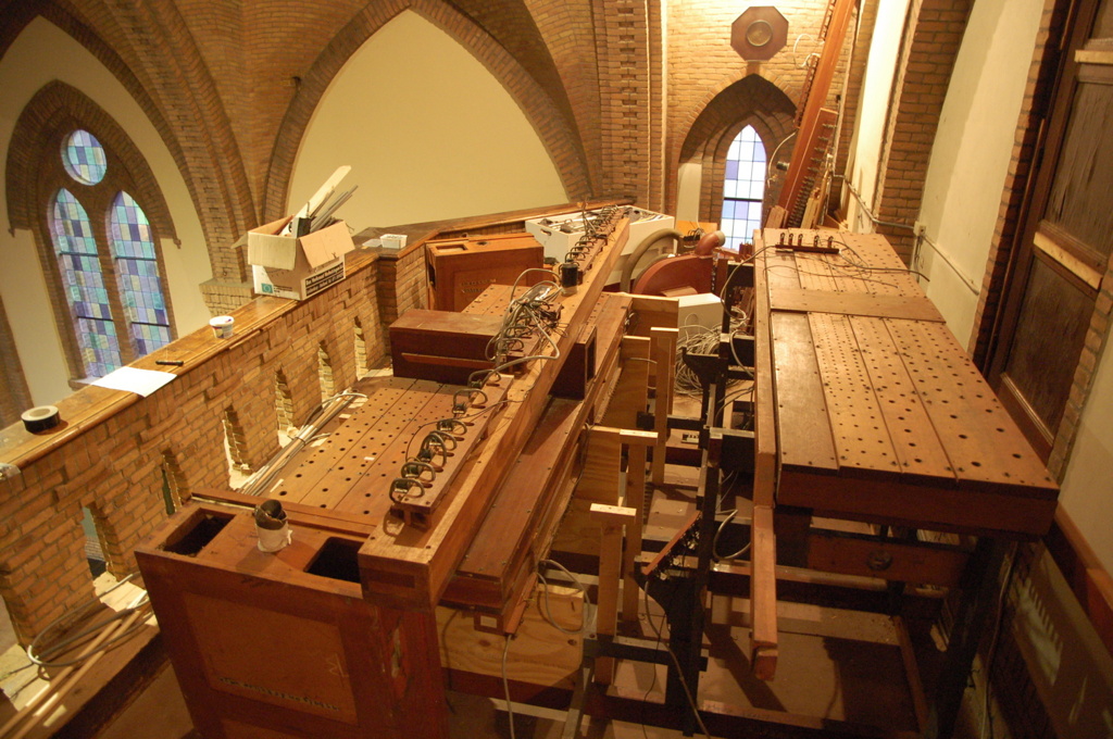
It is a medium to small two manual instrument of Verschueren from Heythuysen, built in the 1950's with a fine character and a rather good Oboe reed, but without a swell box and strings. More details follow with the photos. In the 1990's the organ was moved from the church floor up to the western gallery. The console stayed on the floor and the complete electric action was renewed with modern electronics, as can be seen in the photo below. The whole action signal went now via one thin cable, instead of via a bundle of say 200 wires as with a traditional electric action.

Then I made a plan how to dismantle it. My good friend Gerard helped me some days. The smaller pipes went into softly lined wooden boxes, the larger pipes and other parts were hoisted from the gallery to the church floor on a rope by hand, one by one. All parts were meticulously photographed, at least as far as necessary to document how parts were put together. The heavy parts were placed aside on the gallery. Only the last day the friendly organ builder came and took a ladder lift with him to hoist the windchests and other large and heavy parts to the floor.
It is quite a lot of work. But the whole organ came apart without complications and was transported to my workshop in good order. You never know what you come across, but there was not a single part that puzzled me. However, the tremulant was, as at first sight it looked like a black box. Furthermore, a round zinc wind channel for one of the Subbass windchests ran straight trough a reservoir that had nothing to do with it. I understand 90% of the digital electronics and of the 400 Volt power electrics. I know the man who installed it, so the last 10% will follow without doubt.
The composition of the organ
As can be seen from the first photo above and the one below, the organ consists of two sections. The front section contains the positif, the rear section the great organ. The largest wooden pipes of the Subbass 16' are placed on either side of the great, within the case. The pedal extension pipes are in between the great and positif.
To the right the prospect pipes of the positif section. The pipes you see, to either side, are non-speaking and purely decorative. Almost all pipes in the front prospect, however, speak and belong to the Prestant 8' of the Great Organ. They are are not fed by one of the windchests, but are on their own direct prospect windchest. All prospect pipes are made of zinc, which is electrolytically covered with tin and then more or less varnished, not bad at all. To the left you see the oak case of the Great Organ section, with again a row of prospect pipes. Most of these pipes speak, in this case in the Octave Basse 8' from the Pedal section. The tallest pipe is 330 cm, including foot. You see that these pipes are directly on a separate windchest, with two-stage pneumatic action underneath.
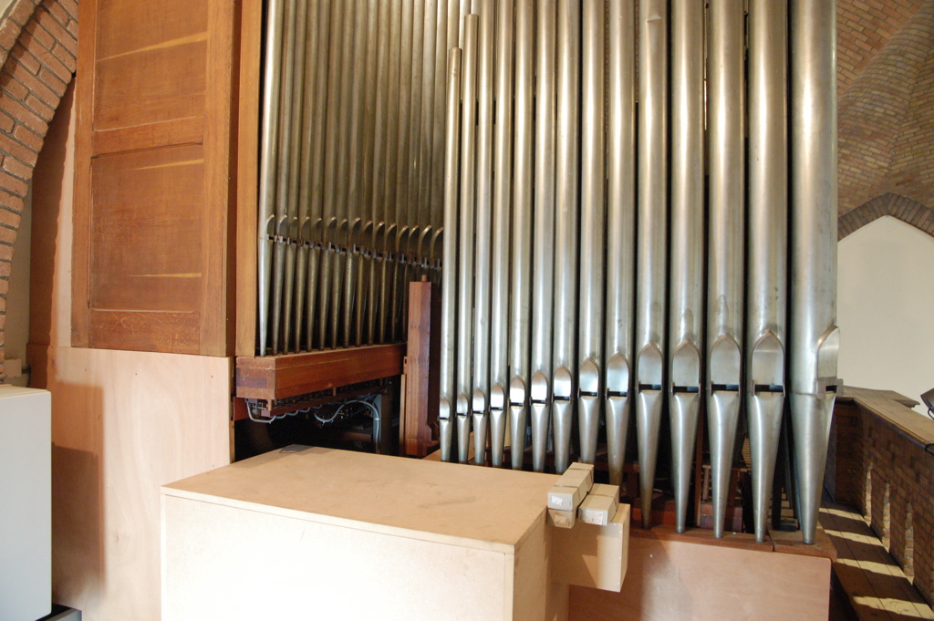
Note that during the replacement of the organ from the church floor to the gallery, the Positif was raised some 60 cm in order to be high enough for the sound and prospect with respect to the stone balustrade. The blower was placed in a new wooden box with sound deadening material inside; it is in front of the photograph.
Here you can see the pipe ranks of the positif section, the second manual, embraced by the prospect pipes. Pipes are placed in C and C# side.

A better view on one side of the windchest of the Positif. To the left is the prospect with the largest pipes of the Prestant 8'. The five largest pipes of the Gedekt 8' and the Blokfluit 4' (conical body) have an other colour: they are made of varnished zinc; the rest is of organ metal (tin and led). The black wood is the frame that keeps the prospect pipes upright and in fact is not easy to dismantle in small parts.

The largest prospect pipes of the Octave Basse 8' from the pedal. The three largest pipes do not speak and are for decoration only. They do not even have a languid. In the middle the direct windschest with the extension pipes of the Subbass 16' and Octave Basse 8' stops. Below you can just see the resonators of the Hautbois (Oboe) reed.

Between the church (or in fact tower) wall and the 'rear' prospect we see the ranks of the Great Organ stops. On the rear the Mahogany pipes of the pedal stop Subbass 16'.

Two details on the pipework. The typical Blokfluit (Recorder) stop, with its conical pipe body.

A fine French style Hautbois or Oboe stop, or should I just say southern, as this style is not only common in France, but also in Belgium and with organ builders from the south of The Netherlands like Verschueren and Vermeulen. Typical is the double cone of the resonator, the upper cone being wider than the main body. This shapes determine the exact sound and timbre of the stop.

The descant of the Hautbois has the typical double block with nut, the southern tuning wire, and the round 'Bertounèche' shallot.

The bass of the Oboe is, as usual, built as a Basson, with the southern style Basson tapered shallots with a tear shaped opening.
Taking the organ apart
The dismantling began with the pipes of the prospects: the front, rear (very unusual to have a rear prospect) and side prospects. Every single pipe was hoisted on a rope by hand to the floor. Then the largest pipes placed along the windchest, sometimes on separate direct windchests, behind the prospect, were removed. This gave a good view on the pipework. Of course also the frame was removed.
Here we see, in front, the direct windchest of the front prospect with the pipes removed. To the left we see the largest pipes placed on separate small windchests. The wind is fed to it by the black zinc tube. The wooden box in the middle contains the stop action.

With the Positif on the front, we see the Great on the rear, with only the five largest pipes of the rear prospect still in place.

We also removed the simple panel work added during the installation of the organ on its new place on the gallery. This reveals some of the wind supply and reservoirs. Also the multiplex stands are visible, used to raise the positif about 60 cm. The positif, and also the great was placed on steel beams, visible in orange-red.

At the left side of the organ, the isolated box with the blower was dismantled.

Every time I had to hoist a heavy part to the floor, I considered the weight and dimensions, how I could tip it over the balustrade and how to have it on the rope. And IF it could be safely done. When I had the largest, 260 cm mahogany Subbass pipe in my hand, I realised that if hoisting down in fact you held it in one hand! You change hands every time, don't you? I tested this and … yes, I could hold the whole 25 kilogramme pipe in one hand …
The oak side panels were taken off and hoisted to the floor. They are quite large and heavy, and the job was done by hand, so this had to be planned and done carefully. Yes, that's me.

Now the pipes were removed. The large and prospect pipes were hoisted to the ground floor and transported separately. Some of the larger pipes were packed in the large wooden box (by Gerard!).
The pipes that fit in the normal size wooden pipe boxes, were packed and stayed on the gallery. By the way, the paper tape labels are not mine! They are in fact not necessary as the stops can be recognised and the tone is stamped in the pipe body.

The Oboe pipes are rather heavy with their massive double blocks.

In this way, four boxes were packed with larger and smaller pipes. As these pipes have a rather high tin content, they can be stacked carefully without too much chance on deformation. I pack the smaller pipes on the bottom, because they are stronger due to their smaller curve radius. Between layers I always use thick curved foam foil.

As soon as all pipes, prospect, prospect frames and cases are dismantled and hoisted to the floor, the heart of the organ sees daylight. This took several days. From left to right: the windchest of the positif manual (the large front prospect windchest has already been removed, you can see it upright in the back), the windchest for the pedal extensions, the windchest of the rear prospect pipes, and the windchest for the great organ. At either side of the great windchest, there is a direct windchest for the ten largest wooden pipes of the Subbass. Note that the racks for the pipes of the positif has already been removed, while the racks of the great are still in position. There are normally not glued but tightly fit. Also note that the stop action of the Positif is higher than its windchest, while the stop action of the Great is underneath and cannot be seen.

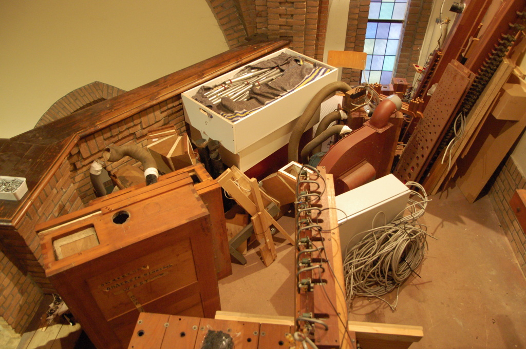
Now the parts under the windchests can be removed: the electric action and wires and the wind reservoirs and wind channels. We see from left to right the blower, the white case with the electronics, the windchest of the Subbass and Great (still with some pipes), the low voltage transformer and rectifier (black box on the wall), the feed to the Subbass windchest in flexible Westaflex, the Great wind regulator reservoir and under it the main reservoir, some pedal extension pipes, the tuning footboard and the windchest of the Positif.

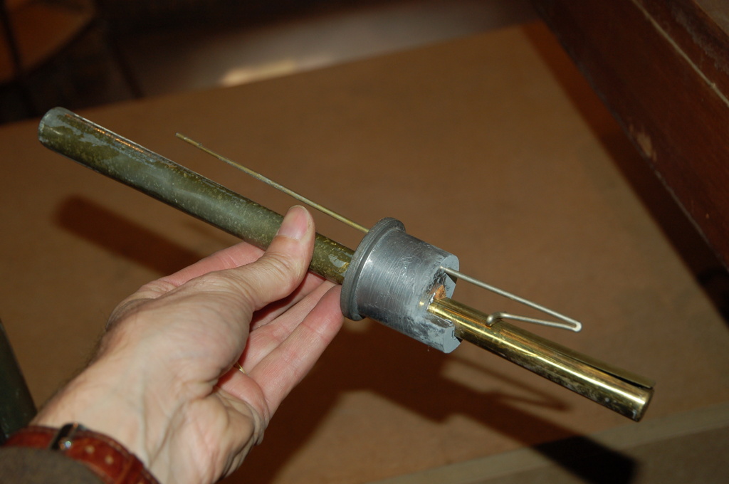
At the right side, the electropneumatic action of the rear prospect windchest and the Subbass chest can be seen. They have a double (two-step) pneumatic action. The black zinc pipe is the wind feed of the right Subbass windchest. The brown box in the middle is the tremulant, working on the complete organ, not just the positif.
By the way, many organ parts and pipes had ugly paper tape with large black letters on it, dating from a past replacing job. From the text, you can derive that the writer did not really understand how the organ was composed.

Rather complex. Still a lot to dismantle.


What is what, what is connected to which and runs to where?

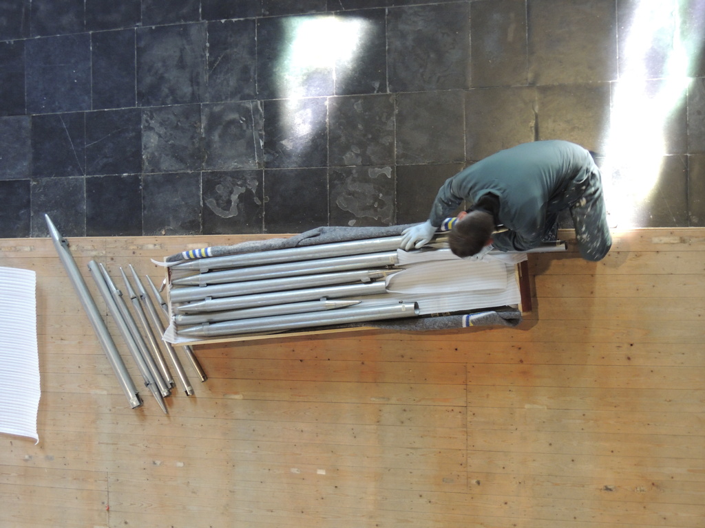
All parts that were to large or heavy to hoist to the ground on a rope, are placed aside for the last day. We then have a ladder lift available. We will need it! On the first picture we see the four pipe boxes, the long windchest of the rear prospect pipes, the two small mahogany windchests of the Subbass, the blower and upright in the corner the windchests of the front prospect pipes and the pedal extensions.

That's it! Apart from the large parts, the windchests are the main challenge for dismantling any organ. In this case (and rather common) the windchest of one section is just one large part. Even both diatonic sides (C and C#) are on the same windchest! These weigh, in this case, about 130 and 140 kilogramme!
The electronic action and electric installation
As said, the conventional electric action of this electropneumatic organ was replaced by electronic action during the replacement of the organ from the church floor to the gallery. Both in the console and near the organ on the gallery, a digital organ electronic system is installed. They communicate via a thin wire, using a fast old-fashioned industry standard serial protocol. By the way, also the low voltage DC power for the console electronics is supplied from the power supply near the organ on the gallery. Furthermore, there is a low voltage wire for switching the organ on and off from the console.
The console was, by the way, removed from its wheeled platform and the first part that came to my workshop. You have seen the electronic board above, but here again:

All functions and switches from the organ console have a separate wire to the analog-digital converters on the board and are mapped to the onboard software. This industry system does not use the well-known diode matrix conversion electronics, but has a separate wire per switch, for example, per manual of pedal key. The whole installation was laid out very neatly!

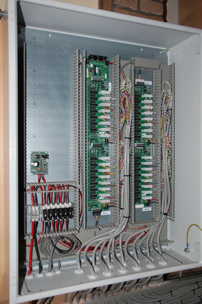
The main electronics board is in the white steel cabinet, mounted on the wall next to the organ. Next to the main electronic control cabinet is the 400 Volt switching gear. And to the right, not visible here because this picture dated from before the dismantling of the organ, is the classic large transformer and rectifier for the high current low voltage power. Again, it is remarkably neatly laid out.

From the main board, one wire runs to every single magnet in the organ, for the keys and stops of the main windchests, but also for the individual pipes placed on the direct windchests, like the prospect pipes, the pedal extension pipes and the Subbass pipes.

I tried to keep the wires connected as far as possible, to prevent a lot of extra work when I built my own organ again, but on the other hand I know the organ will be assembled in a different composition. That means that I will have to extend the electronics, both on the main board and in the console. But even then, it is wise to keep the wires as original as possible. I cut them a couple of decimeters from the magnets, to be able to solder them again conveniently. They were marked.

I collected the wire bundles and kept them near the main board. At the upper right you see the rectifier. The loose black wire is from the blower, which I already disconnected and removed.
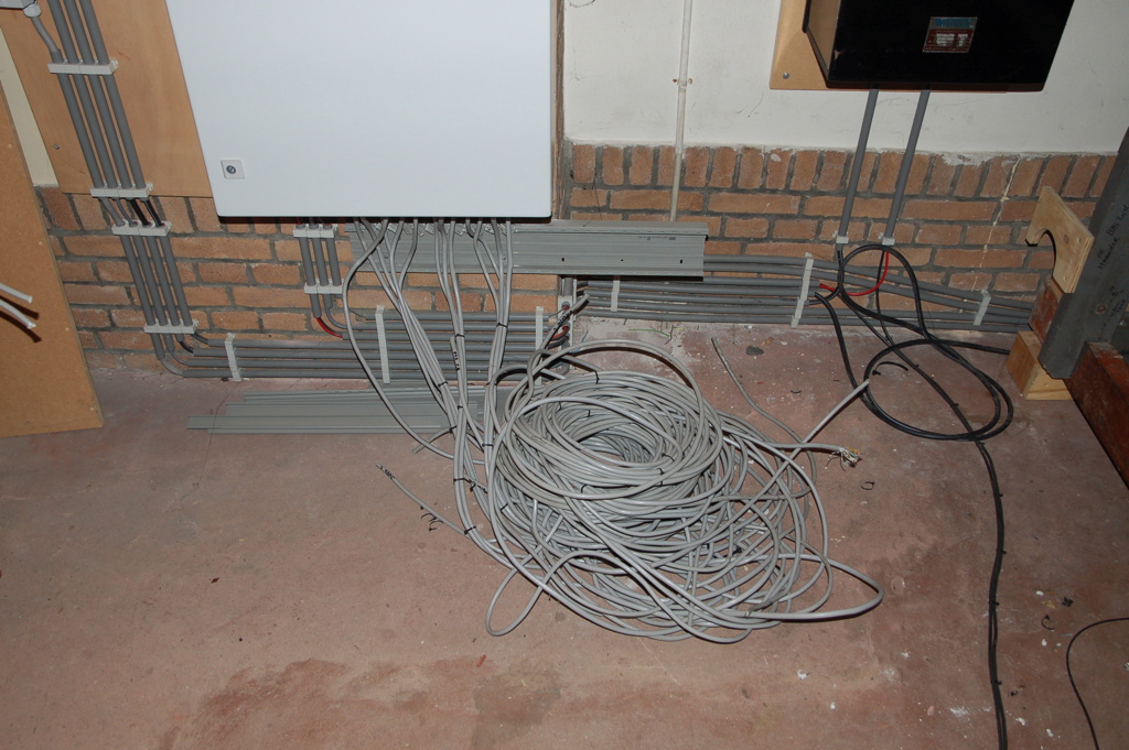
I also dismantled the 400 Volt part of the system. Main switching cabinets.

I not only disconnected and removed the power lines on the wall, but traced them also down into the dusty tower and disconnected them from the mains. By the way, the organ is not accessible from here …


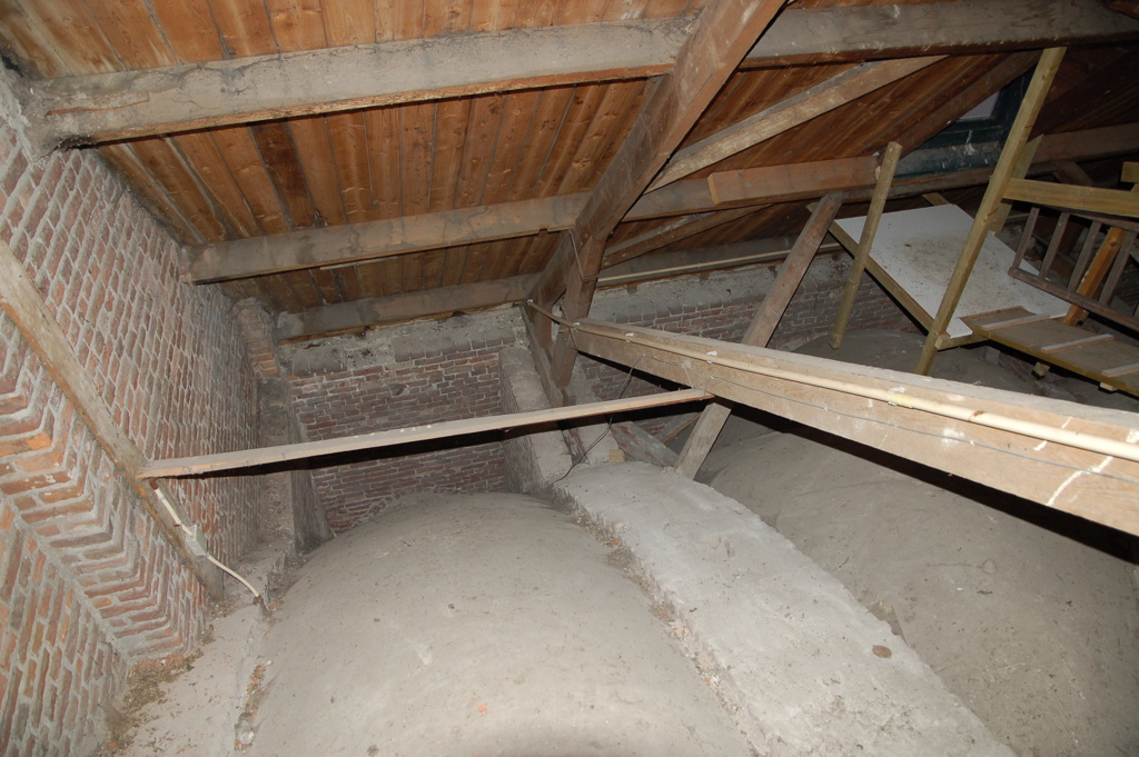
Still that was not enough. The signal cables went upward in the tower, over the stone vaulting, in pipes, to where the console was located. There they ran through the vaulting, over the wall, in a flexible pipe, to the console. All this was dismantled. I was alone and did not feel uncomfortable as I always have liked vaultings, although this was also a physically demanding job. After I finished the job, I understood that the electronics man did not install this himself …

Do you see the yellow PVC pipe? I went down over the brick arc and dismantled the pipes and freed the cables that ran inside them. Under the roof, over the walls and vaultings. Without cutting the wires! That was a challenge, to be honest.
The last job: having the large parts hoisted down and to the workshop
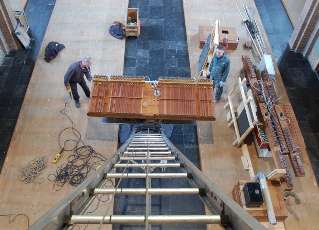
For the final dismantling, my friendly organ builder came to help me and brought a ladder lift with him. We started with the blower, the pipe boxes and the electronics installation cabinet. Here the three direct windchests were lifted conveniently to the church floor.

Some smaller parts. What a mess! No, not really, I know every single part.

The most difficult job: the windchests! These large mahogany boxes were lifted from the frame by a couple of strong men, including me … The cones, electromagnets from tone action, pipe boards and the stop action could not be separated. This object weighs about 130 to 140 kilogramme. It can be lifted by hand, but the difficulty is that you are mostly not in the most effective position to lift a load like this. For example: to get it from the frame on a certain height, then move it over the rest of the frame, and move it over the balustrade on the lift platform. Tough job, really tough!

This is the bottom of the Positif windchest. It is a cone chest and you see the tone electromagnets and the wooden pouch channels running under the windchest, one for each key (except for the highest keys).
Now the frame can be taken apart. It consists of oak beams and steel profiles. This kind of photographs is mainly not for public use, but for myself to ease reconstruction. I made so many photographs that I did almost no labeling.

Some parts were already loaded in the truck. But the most heavy parts still have to be done. From the gallery you have a nice overview. Both windchests are on the rear, on small carriers.

All parts fitted in a small truck and were driven to Dongen. The gallery was cleaned and there was no trace left of this organ whatsoever! The parts are stored in my warehouse in Dongen, waiting to be assembled.
Next page: a main reservoir from 1891
Overview: an organ for my own
Kind regards,
Rens Swart